- 您现在的位置:买卖IC网 > Sheet目录471 > MAX1479EVKIT-315 (Maxim Integrated)EVAL KIT FOR MAX1479 315MHZ
�� �
�
�MAX1479� Evaluation� Kit�
�Layout� Issues�
�A� properly� designed� PC� board� is� an� essential� part� of� any�
�RF/microwave� circuit.� On� high-frequency� inputs� and� out-�
�puts,� use� controlled-impedance� lines� and� keep� them� as�
�short� as� possible� to� minimize� losses� and� radiation.� At�
�high� frequencies,� trace� lengths� that� are� on� the� order� of�
�λ� /10� or� longer� can� act� as� antennas.�
�Keeping� the� traces� short� also� reduces� parasitic� induc-�
�tance.� Generally,� 1in� of� a� PC� board� trace� adds� about�
�20nH� of� parasitic� inductance.� The� parasitic� inductance�
�can� have� a� dramatic� effect� on� the� effective� inductance.�
�For� example,� a� 0.5in� trace� connecting� a� 100nH� inductor�
�adds� an� extra� 10nH� of� inductance� or� 10%.�
�To� reduce� the� parasitic� inductance,� use� wider� traces�
�and� a� solid� ground� or� power� plane� below� the� signal�
�traces.� Also,� use� low-inductance� connections� to� ground�
�on� all� GND� pins,� and� place� decoupling� capacitors�
�close� to� all� VDD� connections.�
�The� EV� kit� PC� board� can� serve� as� a� reference� design�
�for� laying� out� a� board� using� the� MAX1479.�
�Detailed� Description�
�Power-Down� Control�
�The� MAX1479� can� be� controlled� externally� using� the�
�ENABLE� connector.� The� IC� draws� approximately� 0.2nA�
�(at� room� temperature)� in� shutdown� mode.� Jumper� JU1�
�is� used� to� control� this� mode.� The� shunt� can� be� placed�
�between� pins� 1� and� 2� to� enable� the� device.� Remove�
�the� JU1� shunt� for� external� control.� See� Table� 1� for�
�jumper� function� descriptions.�
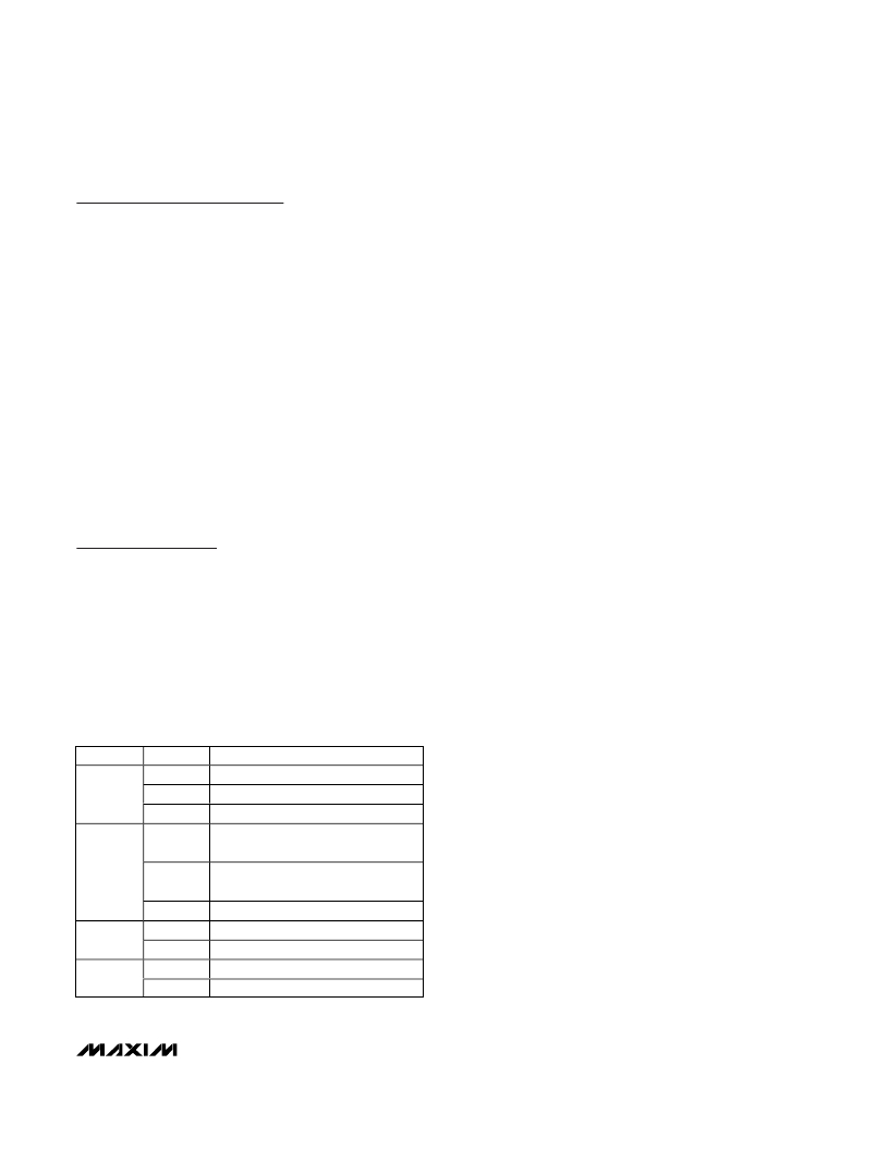
�Table� 1.� JU1� Through� JU4� Jumpers�
�Function�
�Data� Input�
�The� MAX1479� EV� kit� transmits� ASK� and� FSK� data� with�
�data� rates� of� up� to� 100kbps� (ASK)� or� 20kbps� (FSK).�
�JU2� controls� whether� the� MAX1479� transmits� the� ASK�
�carrier� frequency� (or� the� FSK� high� frequency),� turns� off�
�the� PA� (or� transmits� the� FSK� low� frequency),� or� trans-�
�mits� an� external� data� stream.� See� Table� 1.�
�REF_IN� External� Frequency� Input�
�For� applications� where� the� correct� frequency� crystal� is�
�not� available,� it� is� possible� to� directly� inject� an� external�
�frequency� through� the� REF_IN� SMA� (not� provided).�
�Connect� the� SMA� to� a� low-phase-noise� generator.� The�
�addition� of� C18� and� C19� is� necessary� (use� 0.01μF�
�capacitors).�
�Battery� Operation�
�The� MAX1479� EV� kit� can� be� powered� by� an� external�
�power� supply� or� by� the� supplied� 3V� coin-cell� battery.� Set�
�jumper� JU3� to� connect� pins� 2� and� 3� for� battery� operation.�
�RF� Output�
�The� MAX1479� EV� kit� includes� two� SMA� connectors� for�
�RF� output.� RF_OUT� is� a� standard� SMA� and� is� used� to�
�connect� the� PA� output� to� test� equipment.� Output� is�
�matched� to� 50� ?� .� ANTENNA_OUT� is� a� reverse� polarity�
�SMA� and� is� used� to� connect� to� the� 1/4-wave� whip�
�antenna� (not� supplied).� Note� that� resistor� R2� (0� ?� )�
�needs� to� be� added.�
�Modulation� Mode� Input�
�Jumper� JU4� sets� the� mode� of� transmission.� Set� jumper�
�JU4� to� connect� pins� 1� and� 2� for� FSK� mode,� 2� and� 3� for�
�ASK� mode.�
�FSK� Frequency� Deviation�
�The� FSK� deviation� is� set� by� jumpers� JU5� through� JU7.�
�The� maximum� deviation� depends� on� the� PC� board� para-�
�JUMPER�
�JU1�
�JU2�
�JU3�
�JU4�
�STATE�
�1-2�
�2-3�
�N.C.�
�1-2�
�2-3�
�N.C.�
�1-2�
�2-3�
�1-2�
�2-3�
�FUNCTION�
�RF� carrier� transmit� enable�
�Power-down� mode�
�External� power-down� control�
�RF� carrier� transmit� mode� (ASK),�
�FSK� high� frequency� (FSK)�
�PA� off,� PLL� ON� (ASK),�
�FSK� low� frequency� (FSK)�
�External� data� transmit�
�External� supply� operation�
�Battery� operation�
�FSK� mode�
�ASK� mode�
�sitics.� The� EV� kit� max� is� around� 50kHz� (315MHz).� If� very�
�large� FSK� frequency� deviations� are� desired,� use� a� crystal�
�with� a� larger� motional� capacitance� and/or� reduce� PC�
�board� parasitic� capacitances.� One� way� to� reduce� para-�
�sitic� capacitances� on� the� EV� kit� is� to� remove� C14,� C15,�
�and� C16� and� move� the� crystal� closer� to� the� IC.�
�_______________________________________________________________________________________�
�3�
�发布紧急采购,3分钟左右您将得到回复。
相关PDF资料
MAX19700EVKIT
EVAL KIT FOR MAX19700
MAX19985AETX+T
IC MIXER DOWNCONV 36-TQFN-EP
MAX19993ETX+
IC MIXER DOWNCONV 36TQFN
MAX19994AEVKIT#
KIT EVAL FOR MAX19994A MIXER
MAX19995ETX+T
IC DOWNCONVERTER 2CH 36TQFN
MAX19995EVKIT#
EVALUATION KIT FOR MAX19995
MAX19996AEVKIT#
EVALUATION KIT FOR MAX19996A
MAX19996ETP+T
IC MIXER DOWNCONV 20-TQFN-EP
相关代理商/技术参数
MAX1479EVKIT-433
功能描述:射频开发工具 MAX1479 Eval Kit RoHS:否 制造商:Taiyo Yuden 产品:Wireless Modules 类型:Wireless Audio 工具用于评估:WYSAAVDX7 频率: 工作电源电压:3.4 V to 5.5 V
MAX147ACAP
功能描述:模数转换器 - ADC RoHS:否 制造商:Texas Instruments 通道数量:2 结构:Sigma-Delta 转换速率:125 SPs to 8 KSPs 分辨率:24 bit 输入类型:Differential 信噪比:107 dB 接口类型:SPI 工作电源电压:1.7 V to 3.6 V, 2.7 V to 5.25 V 最大工作温度:+ 85 C 安装风格:SMD/SMT 封装 / 箱体:VQFN-32
MAX147ACAP+
功能描述:模数转换器 - ADC 12-Bit 8Ch 133ksps 5.25V Precision ADC RoHS:否 制造商:Texas Instruments 通道数量:2 结构:Sigma-Delta 转换速率:125 SPs to 8 KSPs 分辨率:24 bit 输入类型:Differential 信噪比:107 dB 接口类型:SPI 工作电源电压:1.7 V to 3.6 V, 2.7 V to 5.25 V 最大工作温度:+ 85 C 安装风格:SMD/SMT 封装 / 箱体:VQFN-32
MAX147ACAP+T
功能描述:模数转换器 - ADC 12-Bit 8Ch 133ksps 5.25V Precision ADC RoHS:否 制造商:Texas Instruments 通道数量:2 结构:Sigma-Delta 转换速率:125 SPs to 8 KSPs 分辨率:24 bit 输入类型:Differential 信噪比:107 dB 接口类型:SPI 工作电源电压:1.7 V to 3.6 V, 2.7 V to 5.25 V 最大工作温度:+ 85 C 安装风格:SMD/SMT 封装 / 箱体:VQFN-32
MAX147ACAP-T
功能描述:模数转换器 - ADC RoHS:否 制造商:Texas Instruments 通道数量:2 结构:Sigma-Delta 转换速率:125 SPs to 8 KSPs 分辨率:24 bit 输入类型:Differential 信噪比:107 dB 接口类型:SPI 工作电源电压:1.7 V to 3.6 V, 2.7 V to 5.25 V 最大工作温度:+ 85 C 安装风格:SMD/SMT 封装 / 箱体:VQFN-32
MAX147ACPP
功能描述:模数转换器 - ADC RoHS:否 制造商:Texas Instruments 通道数量:2 结构:Sigma-Delta 转换速率:125 SPs to 8 KSPs 分辨率:24 bit 输入类型:Differential 信噪比:107 dB 接口类型:SPI 工作电源电压:1.7 V to 3.6 V, 2.7 V to 5.25 V 最大工作温度:+ 85 C 安装风格:SMD/SMT 封装 / 箱体:VQFN-32
MAX147ACPP+
功能描述:模数转换器 - ADC 12-Bit 8Ch 133ksps 5.25V Precision ADC RoHS:否 制造商:Texas Instruments 通道数量:2 结构:Sigma-Delta 转换速率:125 SPs to 8 KSPs 分辨率:24 bit 输入类型:Differential 信噪比:107 dB 接口类型:SPI 工作电源电压:1.7 V to 3.6 V, 2.7 V to 5.25 V 最大工作温度:+ 85 C 安装风格:SMD/SMT 封装 / 箱体:VQFN-32
MAX147AEAP
功能描述:模数转换器 - ADC Integrated Circuits (ICs) RoHS:否 制造商:Texas Instruments 通道数量:2 结构:Sigma-Delta 转换速率:125 SPs to 8 KSPs 分辨率:24 bit 输入类型:Differential 信噪比:107 dB 接口类型:SPI 工作电源电压:1.7 V to 3.6 V, 2.7 V to 5.25 V 最大工作温度:+ 85 C 安装风格:SMD/SMT 封装 / 箱体:VQFN-32